

Horizontal Bead Mill Structure: How It's Built and How It Works Inside

Updated: Aug 24
Author: Moeez Ullah Published Date: August 24, 2026
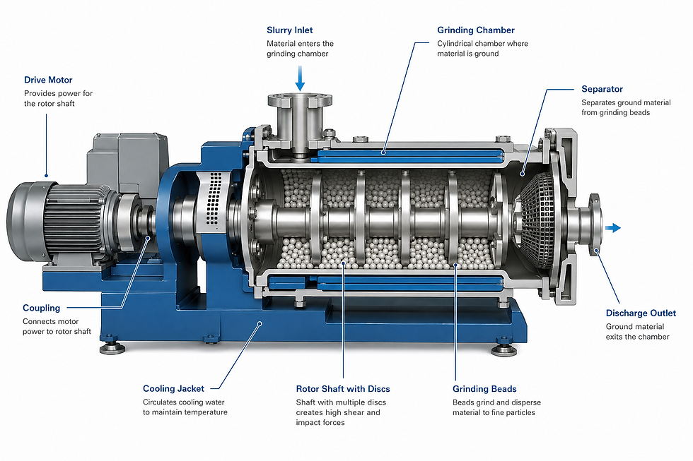
Horizontal Bead Mill Structure: How It's Built and How It Works Inside
Component | Function | Typical Material |
Grinding chamber (cylinder) | Houses beads + slurry, where impact/shear grinding occurs | Alloy steel with ceramic or tungsten carbide lining |
Agitator shaft & discs/pins | Rotates at high speed to fling beads into the material | Hardened alloy, ceramic-coated |
Grinding media (beads) | Physically fracture and disperse particles | Zirconia, glass, or steel beads |
Dynamic separator / screen | Retains beads inside the chamber, releases finished slurry | Slotted disc, gap screen, or centrifugal separator |
Mechanical seal | Seals the rotating shaft against chamber pressure and leakage | Silicon carbide / tungsten carbide double-face seal |
Cooling jacket | Removes heat generated by high-speed friction | Jacketed steel shell with circulating water/glycol |
Feed pump & discharge valve | Moves slurry into and out of the chamber continuously | Diaphragm or gear pump |
If you've ever wondered what actually happens inside the steel cylinder of a horizontal bead mill while it's running, the honest answer is: a lot, in a very small space, very fast. A rotor can spin at 8–14 m/s tip speed while thousands of tiny beads collide with particles up to tens of thousands of times per second. Understanding the internal structure isn't just engineering trivia — it's what tells you why one mill grinds to 100nm consistently and another one clogs, overheats, or leaks after six months.
This guide breaks the machine down part by part, then walks through the process step by step, so you know exactly what's happening between the inlet and the outlet.
What Is a Horizontal Bead Mill?
A horizontal bead mill is a wet grinding and dispersion machine with its grinding chamber mounted horizontally rather than upright. Slurry is pumped in, agitated at high speed against a bed of grinding beads, and pumped out continuously — which is why horizontal mills dominate large-scale, continuous production lines for inks, paints, pigments, battery slurries, and agrochemicals. Because the chamber sits sideways, gravity has almost no effect on where the beads settle, which keeps grinding more consistent across the full chamber than in a vertical design.
The Internal Structure of a Horizontal Bead Mill, Part by Part
1. The Grinding Chamber (Cylinder)

The chamber is the core of the machine cylindrical housing that holds the grinding media and product while the process runs.</cite> Internally it's lined with wear-resistant material (alloy steel, ceramic, or tungsten carbide) because this is the surface taking constant abrasive contact from the beads. A poorly designed chamber leaves "dead zones" where material doesn't circulate — those pockets are where agglomerates survive the whole pass.
2. The Agitator Shaft and Rotor (Disc or Pin Type)

Running through the center of the chamber is the agitator shaft, driven by the motor. Mounted on it are either grinding discs or pins, depending on the model:
Disc-type rotors: flat discs with slots or holes that generate shear and turbulence as they spin, forcing beads outward and material inward.
Pin-type rotors: cylindrical rotors with multiple pins protruding from the surface, delivering high-energy impact and shear forces for efficient grinding and dispersion.
Manufacturers offer a wider range of rotor structures on horizontal mills than on vertical ones — pin type, turbo type, eccentric disc, and combined designs — because the horizontal layout gives more room to tune the rotor to a specific product's viscosity and target fineness.
3. Grinding Media (Beads)

The beads themselves aren't just "filler" — they're the actual grinding tool. <cite index="18-1">Made of ceramic, glass, or steel, the beads spin around inside the chamber and collide with particles, breaking them down through repeated impact until the dispersion is fine and uniform.</cite> Bead diameter, density, and hardness are matched to the target particle size and the abrasiveness of the material being processed — this is a separate decision from the machine's structure, but the internal geometry (chamber width, disc spacing) has to be built around the bead size range the mill is designed for.
4. The Separation System

Once grinding is complete, the finished slurry has to leave the chamber — but the beads must stay inside. This is handled by a separator, and horizontal mills use a few different approaches:
Slit/gap separation, where a narrow gap between rotating and stationary parts lets slurry through but blocks beads.
Screen/mesh separation, where a mesh-shaped screen installed near the outlet allows only the disperse media to pass while blocking the beads.</cite> In more advanced designs, the screen sits inside an internal cavity in the rotor itself, which <cite index="1-1">extends the slurry's moving path and improves dispersion efficiency before final discharge.</cite>
Centrifugal (dynamic) separation, which uses rotational force rather than a physical mesh — this is the preferred option for very fine, nano-scale grinding because it doesn't clog the way a fine mesh screen can under high solids loading.
5. The Mechanical Seal System

Where the rotating shaft exits the pressurized chamber, a seal is required to stop slurry from leaking out and air from getting in. Most conventional horizontal bead mills use a double mechanical seal with a sealing-liquid circulation system to lubricate and cool the seal faces continuously. This is also the single most common source of unplanned downtime on the market: seal wear leads to leakage, contamination, and — with solvent-based or flammable slurries — a genuine safety risk. It's the reason some manufacturers, including Sanxing's SP Series, have moved toward seal-free chamber designs for certain product lines to remove this failure point entirely.
6. The Cooling System
High-speed bead-to-particle collisions generate significant frictional heat, which can degrade heat-sensitive formulations (battery slurries, some pigments) if left unmanaged. A cooling jacket surrounds the grinding chamber, circulating water or glycol to pull heat out during operation, with temperature sensors typically feeding back to a PLC control panel for real-time monitoring.
7. Feed Pump, Inlet, and Discharge
A diaphragm or gear pump continuously feeds pre-mixed slurry into the chamber at one end; ground product exits through the separator at the other. Continuous flow — rather than batch processing — is what makes horizontal bead mills suitable for large production volumes with consistent output quality.
How a Horizontal Bead Mill Works: Step-by-Step Process
Feeding — Pre-dispersed slurry is pumped into the sealed horizontal chamber, which is already filled to a set percentage (commonly 70–90%) with grinding beads.
Agitation and grinding — The rotor spins at high speed, flinging beads into constant, chaotic motion. <cite index="16-1">The material and grinding media are agitated by the high-speed rotating disperser, generating intense collision, friction, and shearing forces between particles and beads that break down agglomerates and reduce particle size.</cite>
Multiple passes (recirculation) — Depending on target fineness, slurry may pass through the chamber once (single-pass) or recirculate through a holding tank multiple times until the desired particle size distribution is reached.
Separation — As ground slurry approaches the outlet, the separator (screen, slit, or centrifugal) filters out the beads, which stay inside the chamber for the next batch of material.
Discharge and cooling — Finished product exits through the outlet while the cooling jacket continues regulating chamber temperature throughout the run.
Disc-Type vs. Pin-Type: Why the Rotor Structure Matters
The rotor design inside the chamber has more influence on output quality than almost any other structural choice:
Disc rotors produce more shear and are generally gentler — well suited to lower-viscosity products like inks and paints where you want fine dispersion without excess heat build-up.
Pin rotors deliver more direct impact energy, which suits thicker, more viscous, or harder-to-disperse materials, including some battery electrode slurries and pigment pastes.
Some manufacturers now offer combined or eccentric-disc rotors specifically to bridge this gap, giving one machine a wider working range across viscosities without a full rebuild.
Why the Internal Structure Determines Real-World Performance
Two horizontal bead mills can look identical from the outside and perform very differently because of what's inside:
Chamber lining wear resistance determines service life and product contamination risk.
Separator type determines the finest particle size you can reliably hit without clogging.
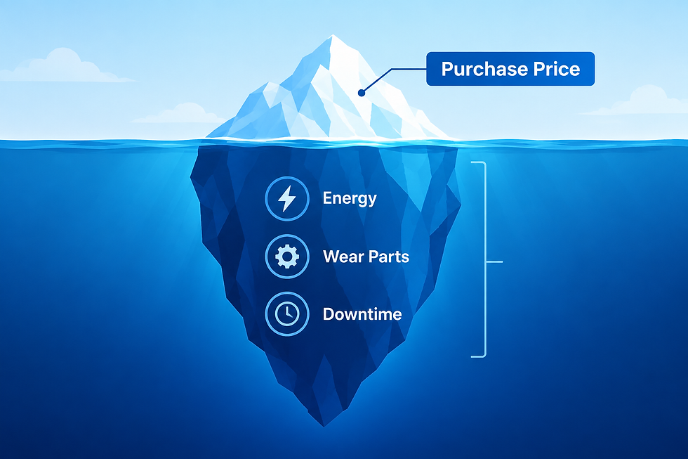
Seal design determines maintenance frequency and downtime risk — arguably the biggest hidden cost in bead mill ownership.
Cooling capacity relative to chamber volume determines whether you can run at full speed on heat-sensitive formulations without degrading the product.
This is why buyers comparing machines on paper specs alone (chamber volume, motor kW) often get surprised in production — the internal engineering is what actually decides throughput and consistency.
Structural Weak Points That Cause Downtime

The most frequent failure points reported across the industry are:
Mechanical seal leakage from wear on the seal faces, especially with abrasive or solvent-based slurries.
Screen/mesh clogging on fine mesh separators when solids content is high or particle size targets are very small.
Disc and lining wear from continuous abrasive contact, gradually reducing grinding efficiency until parts are replaced.
Bearing and shaft wear from prolonged high-speed operation without adequate lubrication or cooling.
Sanxing's WS horizontal bead mill is engineered around these exact points — a wear-resistant lined chamber, a separator matched to the target fineness range, and a cooling system sized to the chamber volume rather than added as an afterthought. For applications where seal downtime is the dominant cost, Sanxing's seal-free SP Series vertical mills remove the mechanical seal entirely; see our guide on the seal-free vertical bead mill for how that design compares for lower-maintenance operation.
Talk to Sanxing About Your Application

If you're evaluating a horizontal bead mill for your production line, our engineering team can help match chamber design, rotor type, and separator to your material's viscosity and target fineness. Explore our WS horizontal bead mill or see how our turnkey EPC powder processing production lines integrate milling into a full process.
Frequently Asked Questions
What is the main difference between a horizontal and vertical bead mill's internal structure?
A horizontal mill's chamber and rotor shaft run sideways, so beads distribute evenly across the chamber regardless of gravity, while a vertical mill's chamber stands upright and relies more on flow dynamics to keep beads suspended.
What material are the beads inside a horizontal bead mill made of?
Most commonly zirconia (zirconium oxide) ceramic, glass, or steel — chosen based on the target fineness, product purity requirements, and abrasiveness of the material being ground.
How fine can a horizontal bead mill grind?
Depending on chamber design, separator type, and bead size, horizontal bead mills can reduce particles from tens of microns down to the sub-200-nanometer, nano-scale range.
What causes a horizontal bead mill to leak?
The most common cause is mechanical seal wear at the point where the rotating shaft exits the pressurized chamber — which is why seal design and maintenance schedule matter as much as the grinding chamber itself.
External Links Used (authoritative, non-competitor)
ResearchGate — working principle diagram reference for grinding chamber/separator concepts (cite generally, don't reproduce the figure)
General engineering explainer (Allwin Grinding basics guide) for the gravity/vertical-vs-horizontal comparison point


Comments